Spiegazione della polarità delle cassette MPO: Tipo A / AF / B1 / B2 / U
Sep 24, 2026Cablaggio data center in MPO-LC: la polarità della cassetta definisce la mappatura della fibra tra la porta trunk MPO e le porte LC duplex frontali. Determina se i percorsi di trasmissione e ricezione corrispondono; un errore comporta il mancato stabilimento del collegamento. Esistono cinque polarità principali (A, AF, B1, B2 e U), ciascuna corrispondente a un diverso metodo di cablaggio ANSI/TIA-568.
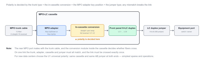
Figura 1 Cassetta MPO-LC: struttura interna e punto di impostazione della polarità
Type-A segue il Metodo-A, abbinando un adattatore di tipo A (Key-Up/Down) a un trunk dritto di tipo A. Le fibre passano dirette all'interno della cassetta, conservando la sequenza 1–12. L'implementazione è semplice, ma le due estremità richiedono bretelle differenti (AA a un'estremità, AB all'altra), rendendo complessa la manutenzione. Viene utilizzata principalmente in installazioni LC duplex legacy 10G/25G.
Type-AF utilizza anch'essa un adattatore di tipo A e un trunk di tipo A; la differenza sta nel fatto che la cassetta esegue l'inversione delle coppie (1↔️2, 3↔️4) internamente, scambiando Tx/Rx su ciascuna porta duplex. Utilizzata in coppia con Type-A, consente a entrambe le estremità di impiegare bretelle AB, semplificando il permutamento in loco. È adatta per ammodernamenti MPO-LC ad alta densità.
Type-B1 e B2 seguono il Metodo-B; entrambe utilizzano un adattatore di tipo B (Key-Up/Up) con un trunk invertito di tipo B. B1 è passante/dritta all'interno della cassetta, pertanto l'inversione Tx/Rx viene eseguita dall'adattatore; è la polarità di tipo B più comune. B2 inverte l'intera sequenza 1–12 all'interno della cassetta, per cui l'inversione è gestita dalla cassetta stessa e deve essere abbinata a un trunk dritto (un trunk invertito effettuerebbe una doppia inversione, interrompendo il collegamento). B2 è solitamente una soluzione proprietaria del produttore con scarsa intercambiabilità. Non mischiare mai le due tipologie.
Type-U (U1/U2) è la polarità universale introdotta dallo standard ANSI/TIA-568.3-E (2022) ed è la scelta preferenziale per i nuovi impianti. U1 e U2 richiedono entrambe un trunk di tipo B e bretelle duplex AB; entrambe le estremità possono utilizzare la stessa cassetta di tipo U, senza necessità di distinguere i tipi di cassetta. La differenza risiede nell'adattatore: U1 utilizza un adattatore di tipo A, supporta sia la modalità multimodale sia monomodale ed è comunemente usata per la scomposizione/aggregazione dei moduli; U2 impiega un adattatore di tipo B ed è utilizzata principalmente per canali duplex multimodali. I relativi componenti non sono intercambiabili.
Tabella 1 Guida alla selezione rapida per le sei tipologie di polarità delle cassette
|
Polarità |
Metodo di cablaggio |
Adattatore MPO |
Cavo trunk |
Mappatura interna alla cassetta |
Bretelle duplex |
Uso tipico |
|
Type-A |
Metodo-A |
Tipo A Key-Up/Down |
Tipo A dritto |
Passante (dritto) |
AA a un'estremità; AB all'altra |
Legacy 10G/25G duplex |
|
Type-AF |
Metodo-A |
Tipo A Key-Up/Down |
Tipo A dritto |
Inversione di coppia (1↔️2, 3↔️4) |
AB a entrambe le estremità |
Ammodernamento MPO-LC ad alta densità |
|
Type-B1 |
Metodo-B |
Tipo B Key-Up/Up |
Tipo B invertito |
Passante (dritto) |
AB a entrambe le estremità |
Polarità di tipo B più comune |
|
Type-B2 |
Metodo-B |
Tipo B Key-Up/Up |
Tipo A dritto |
Inversione completa (1↔️12) |
AB entrambi le estremità |
Design specifico del fornitore |
|
Tipo-U1 |
Metodo-U1 |
Tipo A con chiave in alto/basso |
Tipo B invertito |
Conversione U1 |
AB entrambi le estremità |
Breakout multi-modo + singolo modo |
|
Tipo-U2 |
Metodo-U2 |
Tipo B con chiave in alto/alto |
Tipo B invertito |
Conversione U2 |
AB su entrambe le estremità |
Canali duplex multi-modo |
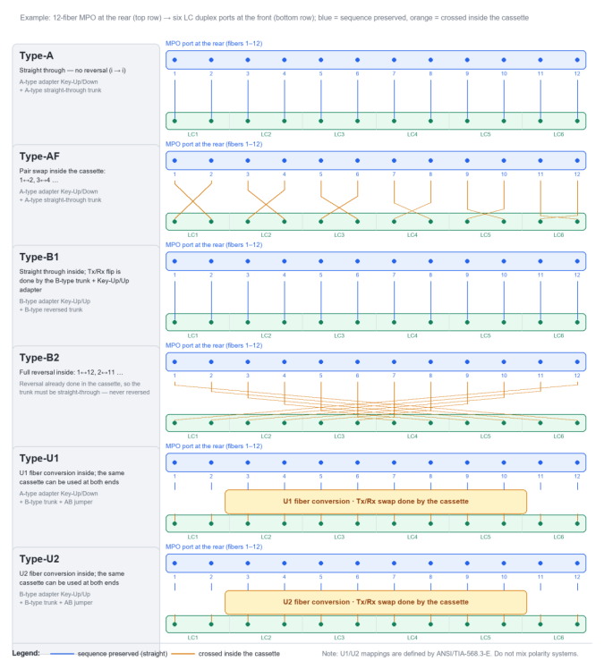
Figura 2 Mappatura della fibra nella cassetta dei sei tipi di polarità (MPO a 12 fibre → 6×LC duplex)
Regola ingegneristica: mantenere un sistema di polarità per collegamento. Non mescolare mai A/AF, B1/B2 o U tra i sistemi. Per i nuovi data center preferire U1; per i retrofitting legacy abbinare A/AF o B1 secondo necessità.
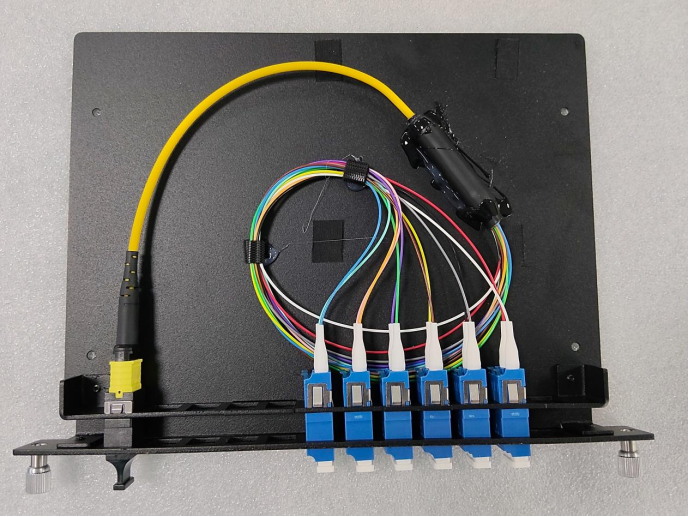
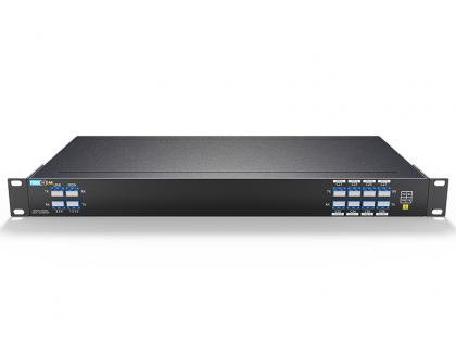
Figura 3 Cassetta MPO-LC sul campo: MPO a 12 fibre sul retro, diramato a sei porte LC duplex sul fronte
Domande Frequenti (FAQ)
D1 Come posso identificare rapidamente quale polarità utilizza una cassetta?
Inizia con la posizione della chiave dell'adattatore MPO: Key-Up/Down (tipo A) di solito significa A, AF o U1, mentre Key-Up/Up (tipo B) di solito significa B1, B2 o U2. Quindi controlla l'etichetta della cassetta e se il trunk è dritto o invertito. Se la cassetta scambi le fibre internamente non può essere visto dall'esterno, quindi confermalo con la tabella di mappatura delle fibre del fornitore e verifica fibra per fibra con una sorgente di luce rossa sui collegamenti critici.
D2 Il Tipo-A e il Tipo-AF sono entrambi Metodo-A: perché devono essere usati in coppie?
In una cassetta di Tipo-A le fibre passano direttamente e l'inversione Tx/Rx viene eseguita dal bretella; il Tipo-AF sposta quell'inversione all'interno della cassetta. Utilizzati insieme, entrambi gli stili del collegamento possono utilizzare bretelle AB, senza la necessità di tracciare quale estremità richiede AA. Se l'intero collegamento utilizza solo A o solo AF, viene invertito una volta di troppo o una volta troppo poco, e Tx/Rx finisce comunque per essere incrociato.
D3 Perché è consigliato il Tipo-U1 per i nuovi data center?
Con U1/U2, entrambe le estremità utilizzano la stessa cassetta e la stessa bretella AB, quindi non esiste una "cassetta di estremità A" rispetto alla "cassetta di estremità B". È necessaria una sola parte di ricambio, rendendo l'espansione e la sostituzione dei guasti il più semplice possibile. U1 utilizza un adattatore di tipo A e copre sia la modalità multipla che la modalità singola. Nota che U1 e U2 utilizzano adattatori diversi e i loro componenti non sono intercambiabili: non mescolarli su un unico collegamento.
D4 Cosa succede se la polarità è errata e come posso risolverla?
In genere il collegamento non si attiva o perde pacchetti frequentemente, poiché i ricetrasmettitori alle due estremità non riescono a stabilire un collegamento. Risolvi i problemi in questo ordine: (1) conferma che i tipi di polarità della cassetta a entrambe le estremità corrispondano effettivamente; (2) controlla se il trunk è dritto o invertito; (3) controlla se i bretelle sono AA o AB e se entrambe le estremità sono coerenti; (4) verifica la mappatura fibra per fibra con una sorgente di luce rossa o un optical power meter, quindi sostituisci la parte rilevante una volta individuata la posizione della fibra difettosa.

Indirizzo : Room 901, Building 6, JD Smart Industrial Park, No. 128, Juhua Stone Avenue, Huashan Town, Huadu District, Guangzhou City
Tel : +86 15989256178
Whatsapp : +86 15914235380
E-mail : sales@fiberwdm.com